English
  Deutsch
  Español
  Türkçe
  Italiano
  Русский
  Français
  Português
  العربية
  Українська
  Nederlands
 A tow ball bike rack provides a compact way to transport bicycles at the rear of a vehicle without requiring roof-mounted carriers. For a clamp-on design, the rack connects directly to the vehicle’s tow ball and carries the bicycles through a relatively simple but highly interconnected structure.
In a 3-bike tow ball rack, the complete system typically involves three key areas:
Tow-Ball Connection → Main Frame → Bike Support System
The tow-ball clamp establishes the connection with the vehicle. The main frame transfers the bicycle loads toward that connection point, while the support arms and cradles determine how the bicycles are positioned and carried.
This means the performance of the rack cannot be judged from one component alone. Clamping stability, frame geometry, support-arm rigidity, cradle positioning and bicycle spacing all need to work together.
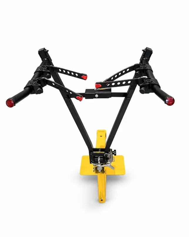
How a Tow Ball Bike Rack Carries the Load
Although the rack has relatively few major components, each one performs a specific function within the load path.
For this type of 3-bike rack, the structure can be understood as:
Bicycles → Bike Cradles → Support Arms → Main Frame → Tow-Ball Clamp → Vehicle Tow Ball
| Component | Main Function | Key Design Consideration |
| Tow-Ball Clamp | Connects the rack to the vehicle | Stable contact and controlled movement |
| Main Frame | Transfers bicycle loads toward the mounting point | Rigidity and geometry |
| Horizontal Brace | Helps stabilize the main frame | Position and alignment |
| Support Arms | Carry the bicycles away from the main frame | Length, rigidity and spacing |
| Bike Cradles | Locate and support bicycle frames | Positioning, grip and frame protection |
| Joints & Fasteners | Connect structural components | Strength and assembly consistency |
| Surface Finish | Protects the steel structure | Coverage and durability |
The important point is not simply whether each individual component is strong enough.
The rack works as a complete structural system. A change in support-arm length, bicycle position or frame geometry can also change the loads transferred to the lower mounting point.
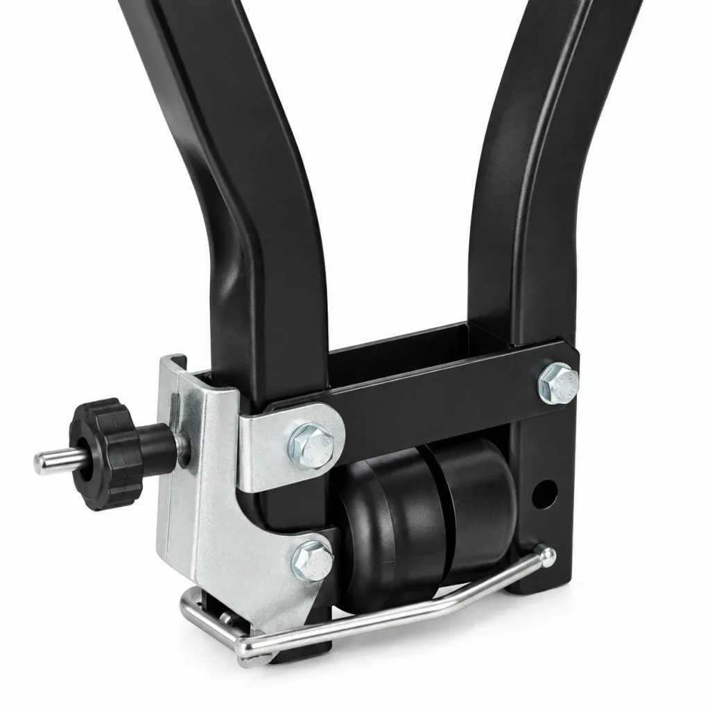
1. Tow-Ball Clamp: The Main Vehicle Connection
The tow-ball clamp forms the connection between the rack and the vehicle.
Because the bicycles are positioned above and behind this mounting point, the connection needs to control not only vertical load but also unwanted movement of the rack.
Starting, braking, cornering and road irregularities can introduce forces in different directions.
The effectiveness of the connection therefore depends on factors such as:
- clamp geometry;
- contact with the tow ball;
- adjustment mechanism;
- rigidity of the surrounding structure;
- alignment between the clamp and main frame.
Simply increasing tightening force does not replace suitable contact geometry.
The clamp needs to engage with the intended tow-ball configuration in a controlled and repeatable way.
Compatibility should also be defined according to the actual product specification. A tow-ball-mounted design should not automatically be assumed to fit every tow-ball configuration.
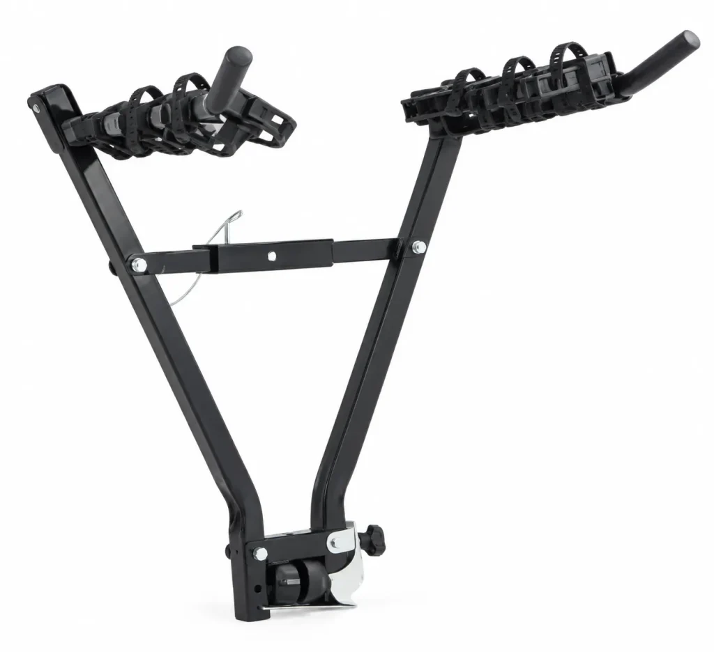
2. Frame Geometry Determines How Loads Reach the Vehicle
The main frame connects the bicycle-supporting section at the top with the tow-ball mounting point below.
On this rack, the V-shaped frame creates a wider upper structure for the two support arms while concentrating the lower structure toward the mounting area.
This geometry forms an important part of the load path.
The frame needs sufficient rigidity to control bending and unwanted movement while carrying bicycles behind the vehicle.
Its performance depends on more than tube thickness alone.
Relevant factors include:
- tube dimensions;
- steel specification;
- frame geometry;
- bending accuracy;
- joint positioning;
- horizontal-brace location;
- alignment with the lower clamp.
The horizontal brace also helps maintain the relationship between the two sides of the frame.
The objective is not simply to use heavier tubing. A well-designed frame uses its geometry and material efficiently so that the complete structure remains practical without unnecessary weight.
3. Support Arms and Cradles Control Bicycle Positioning
The two upper support arms form the main carrying area of this style of bike rack.
Their length, spacing and rigidity determine where the bicycles sit relative to the main frame.
The individual cradles then establish the actual contact points with the bicycle frames.
A good support layout therefore needs to address two different requirements:
supporting the bicycle load and maintaining practical bicycle positioning.
Cradle Position Matters
Cradle position affects:
- spacing between bicycles;
- frame support points;
- bicycle orientation;
- load distribution across the support arms;
- loading and unloading.
The cradle surface is also a direct interface with the bicycle.
Its shape and material should provide useful grip while avoiding unnecessary direct contact between the bicycle frame and the steel support structure.
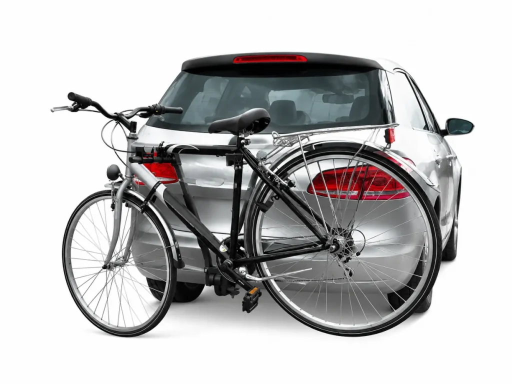
4. Why Three-Bike Spacing Matters
A 3-bike tow ball rack introduces a challenge that is less significant on a single-bike carrier: several bicycles need to occupy the same compact carrying area.
This is not simply a question of fitting three cradles onto the support arms.
Different bicycles can have different:
- frame geometries;
- handlebar widths;
- pedal positions;
- wheel sizes;
- component layouts.
As a result, adjacent bicycles can create potential contact points even when the distance between the cradles appears sufficient.
Cradle Spacing Is Only Part of the Solution
Bicycle spacing needs to be considered together with how each bicycle is positioned.
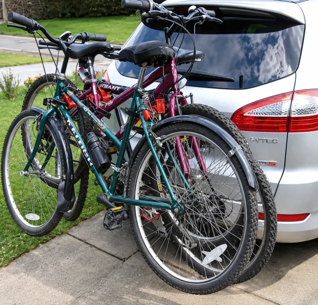
For example, handlebars or pedals from adjacent bicycles may occupy overlapping areas even when their frames are separated.
The relationship is therefore closer to:
Cradle Position + Bicycle Orientation + Bicycle Spacing = Practical Multi-Bike Layout
This is one reason the complete three-bike configuration matters during product development.
The outer bicycle also sits farther from the main frame than the innermost bicycle, creating a different mechanical effect on the support arms.
In simplified terms, the farther the load is positioned from the main frame, the greater the leverage acting on the supporting structure.
For a three-bike rack, the design therefore needs to consider:
Bike Weight + Bike Position + Support-Arm Length + Frame Rigidity + Tow-Ball Connection
5. Vehicle Movement Changes the Loads on the Rack
A tow-ball bike rack does not operate under purely static conditions.
During vehicle use, the structure can experience repeated movement from:
- acceleration;
- braking;
- cornering;
- road vibration;
- uneven road surfaces.
Because the bicycles are positioned behind the mounting point, these movements affect the complete structure from the cradles down to the tow-ball connection.
| Structural Area | Role During Transport |
| Bike Cradles | Maintain bicycle position |
| Support Arms | Carry bicycle loads away from the frame |
| Main Frame | Transfers loads toward the mounting point |
| Horizontal Brace | Helps maintain frame geometry |
| Lower Frame Joint | Transfers loads into the clamp area |
| Tow-Ball Clamp | Connects the complete rack to the vehicle |
| Fasteners | Maintain structural connections |
This is why a maximum load figure alone cannot describe every aspect of rack performance.
The location of the bicycles, support-arm geometry and rigidity of the complete structure also influence how the rack behaves during transport.
6. Manufacturing Accuracy Matters in a Multi-Bike Rack
Once the product structure has been established, manufacturing consistency becomes important.
For this type of rack, several production details directly affect the geometry of the finished product.
V-Frame Symmetry
The left and right sides of the V-shaped frame need to maintain consistent bending angles and dimensions.
Variation can affect the position of the support arms, horizontal brace and lower mounting structure.
Left and Right Support-Arm Alignment
The two support arms need to remain correctly positioned relative to each other.
Differences in height, angle or spacing can affect how the bicycles sit across the rack.
Cradle Position Consistency
On a three-bike model, the location of each cradle contributes to bicycle spacing.
Consistent mounting positions therefore help maintain the intended layout from one production unit to another.
Clamp-to-Frame Alignment
The lower mounting structure should remain correctly aligned with the main frame.
Variation in this area can influence the installed position of the entire rack.
Welding and Joint Consistency
Welded areas and mechanical connections need to maintain the approved geometry rather than pulling the structure out of alignment during fabrication.
Fixtures can be particularly useful for controlling repeatable frame geometry during batch production.
Surface Coating Around Joints
Because the rack is used outside the vehicle, protective finishing needs consistent coverage.
Areas around welds, joints, tube ends, holes and other exposed sections deserve particular attention.
These details are what allow an approved prototype to become a repeatable production product.
Key Specifications to Define Before Production
For a tow-ball bike rack project, the main product requirements should be defined before sample approval and mass production.
| Specification | What Needs to Be Defined |
| Bike Capacity | Number of bicycles |
| Required Working Load | Target total load |
| Tow-Ball Compatibility | Intended mounting specification |
| Main Frame | Material, tube dimensions and geometry |
| Support Arms | Length, position and structural requirement |
| Bike Cradles | Quantity, spacing, material and retention method |
| Bicycle Spacing | Intended distance between carrying positions |
| Surface Finish | Coating and color |
| Product Assembly | Fully or partially assembled |
| Branding | Logo, labels and product identification |
| Packaging | Carton configuration and product protection |
These specifications should not be treated as completely independent variables.
For example, changing bicycle spacing may require changes to support-arm length. Changing support-arm length can influence leverage on the main frame. Increasing the required load may also affect structural requirements elsewhere in the rack.
A multi-bike carrier is therefore best developed as a complete system rather than a collection of separate components.
Developing a Tow Ball Bike Rack with EZLEE
For tow ball bike rack projects, EZLEE can work from an existing product, technical drawing or target specification to develop the main product requirements.
For a 3-bike design, this can include the tow-ball clamping structure, V-frame geometry, support-arm dimensions, bicycle spacing, cradle configuration and required working load.
Once the structural design has been confirmed, surface finish, color, product labels, private-label branding and packaging can be developed according to the project requirements.
EZLEE supports OEM and ODM projects from sample development through repeat batch production, with particular attention to maintaining the approved frame geometry, component positioning and assembly across production units.
Looking for a tow ball bike rack for your product range? Contact EZLEE with your reference product, drawing or target specifications to discuss your project.